Map processing
Map processing relies on a set of options. Here we describe what and how these options can be tweaked. The underlying toolbox used to process the maps are the Whitebox tools.
To consider:
Open channel / sewage network vs. a closed network. An open sewage network’s flow follows surface elevation, while the flow of a closed sewage network is declared by the editor of the map.
Sewage network clean-up (yes/no) and strength.
DEM smoothening filter algorithm and strength. Available algorithms are: none, mean, median, gaussian blur, preserve.
Single-cell pit removal strategy. Available strategies are: fill, breach.
Stream burning strategy and strength. Available strategies are: relative, absolute and fill-burn.
Removal of artificially raised values along riverbeds (such as bridges).
Snapping distance of sites to nearby waterways.
Water accumulation threshold for a pixel to be considered part of a drainage line, with/without standard deviation stretch (normalization step).
Catchment buffering distance around closed sewage lines.
Processing options
Next to the input data that impacts the map processing, users can tweak certain options of the map configuration in case the default ones do not deliver satisfying results in the chosen area of the map. The configuration of map options holds the same significance as map input data and changes made to the default configuration are bound to a version of a map.
Hydrological conditioning of Digital Elevation Models (DEM)
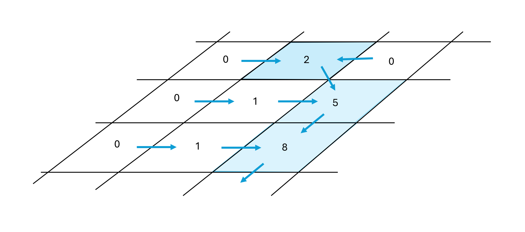
Burning streams
Burning streams enforces the drainage along known waterways. DEM potentially have unwanted raised artifacts or depressions preventing the proper gravitational flow of surface water, for instance caused by the height of buildings or vegetation (if not using a digital terrain model). Very flat terrain and small slopes can cause the delineation of drainage lines to be imprecise. Those issues might lead to the wrong delineation of drainage lines. Part of the hydrological conditioning therefore is to enforce existing waterways into the DEM by a process described as ‘burning’ or ‘engraving’ known river lines into the DEM grid. By default, rivers in a map (manual ones or OpenStreetMap ones) are burned into the DEM.
Stream burning method
Burning waterways into a DEM can be performed in several ways:
By lowering all cell height values along river lines by a specified fixed offset (relative approach).
By resetting all cells along the line to the same (absolute) minimum value, derived from the lowest cell value in the grid.
By using the ‘FillBurn’ algorithm (Saunders, 1999) which ensures that the stream burning offset value is only one unit deeper than the amount of the maximum fill height.
Read more about the FillBurn (Whitebox) algorithm.
Stream burning depth
Specify an offset (in meters) that is subtracted from all stream grid cells. This option only applies to the relative approach of burning streams.
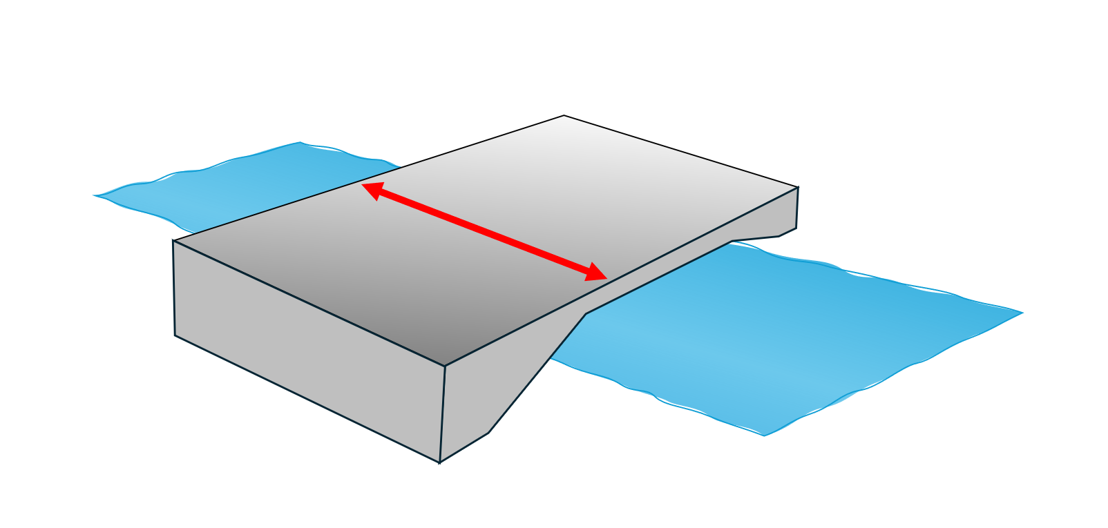
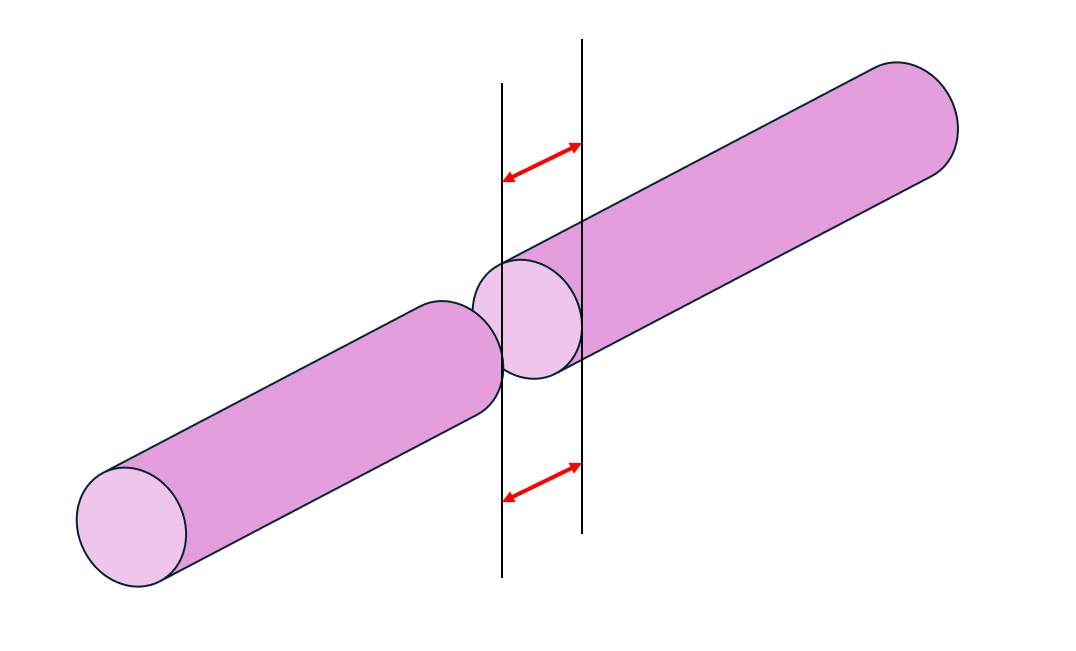
Remove river crossings
River crossings (bridges) often create raised grid cell artifacts in a DEM that function as a barrier against the gravitational flow of water. When a map uses a river source, this option removes such artificial barriers at river / road intersection points, whenever the data is present in OpenStreetMap by decrementing the elevation of grid cells along the river flow direction. Read more about removing river crossings with Whitebox here.
River crossings width
Specify a maximum road embankment width. This influences the width range (along the river) in which the tool tries to decrement the elevation of raised grid cells (caused for instance by bridges)
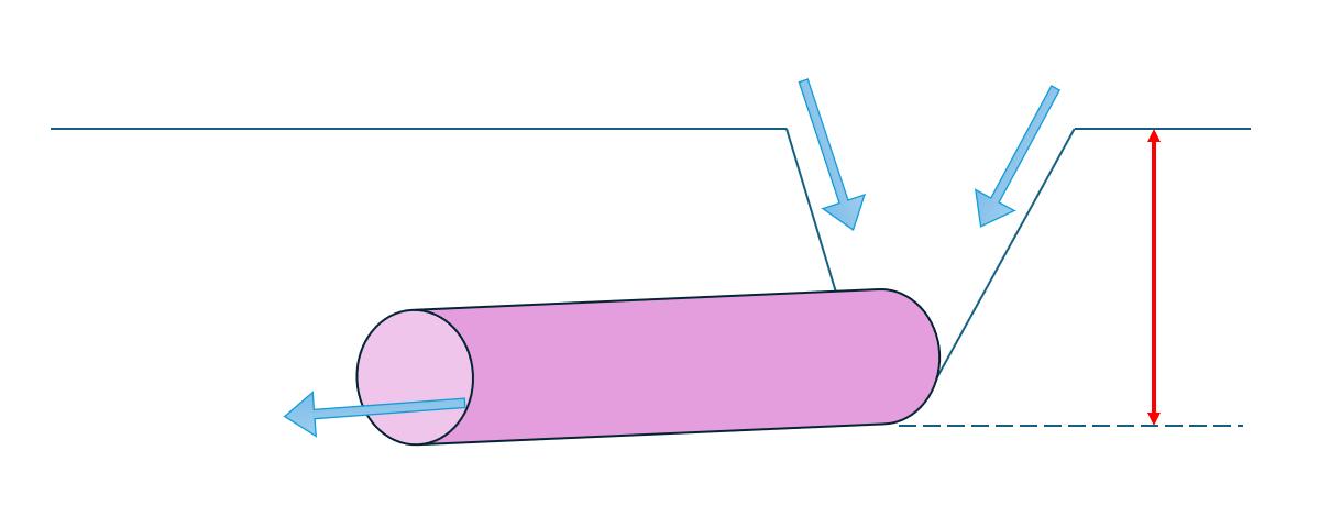
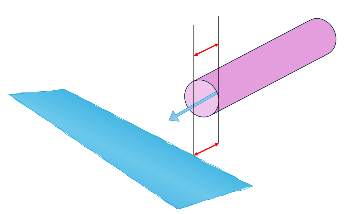
Burn inlets
Enforces drainage flow towards the inlets of sewage pipes. Maps with sewage networks use this option to create artificial sink structures in the elevation grid. This attracts surface flow towards inlet points of a sewage network.
Sink depth
Specify the depth (in meter) of artificially created sink structures at sewage network inlets.
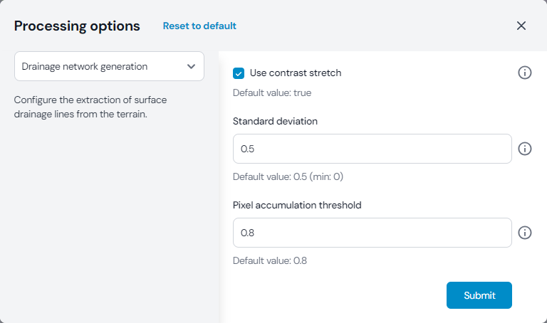
Drainage network generation
Use contrast stretch
Improves drainage line extraction from a flow accumulation grid. Drainage lines are derived by looking at the accumulative flow into a cell. At a certain threshold value, we assume open surface flow in this cell. Because of the different topography of landscapes, it is hard to come up with a generally valid threshold for maps around the globe. Image normalisation (in this case a standard deviation contrast stretch) is therefore used to create a normalized value range of flow accumulation. This allows to work with the same threshold value across many maps. If this option is deactivated, drainage line extraction works based on the actual absolute accumulative cell count. Read more about the standard deviation contrast stretching (Whitebox) here.
Standard deviation
Specify the factor of standard deviations to be used in determining the lower-tail and upper-tail clip values.
Pixel accumulation threshold
Specify the threshold value for grid cells to be distinguished as drainage lines. When using the default standard deviation contrast stretching, all grid cells with a cumulated flow above ‘0.8’ are considered as being drainage lines. If not using contrast stretching, an absolute threshold value for cumulated flow needs be specified. This value expresses the minimum number of upstream cells (directing flow towards a grid cell) before considering it as a drainage cell.
Sewage network
Fix sewage gaps
Digitized sewage networks often lack complete geometric connectivity and small gaps between line endings prevent the processing to build a proper graph from the input data. In the watershed delineation, those network segments are then missed out, because the runoff cannot flow through disconnected pipes. These gaps are mostly in sub-meter scale. Enable to automatically repair disjoint sewage lines when the gaps are within a specified maximum gap distance.
Gap distance
Change the maximum gap distance (in meter) if a network has disjoint lines, but beware of setting too large distances. The processing will otherwise untruly establish connections between nearby sewage lines which do not exist in reality.
Extend sewage lines
Similar to digitization errors within sewage networks, sewage lines that are supposed to end in a lake or river are sometimes geometrically disjoint from their downstream sinks. Enable to automatically repair such disjoint sewage lines by extending them towards nearby rivers and lakes if the distance to those does not exceed a specified maximum distance (in meter).
Extension distance
Specify the maximum distance (in meter) for extending sewage lines to nearby rivers or lakes.
Watershed delineation
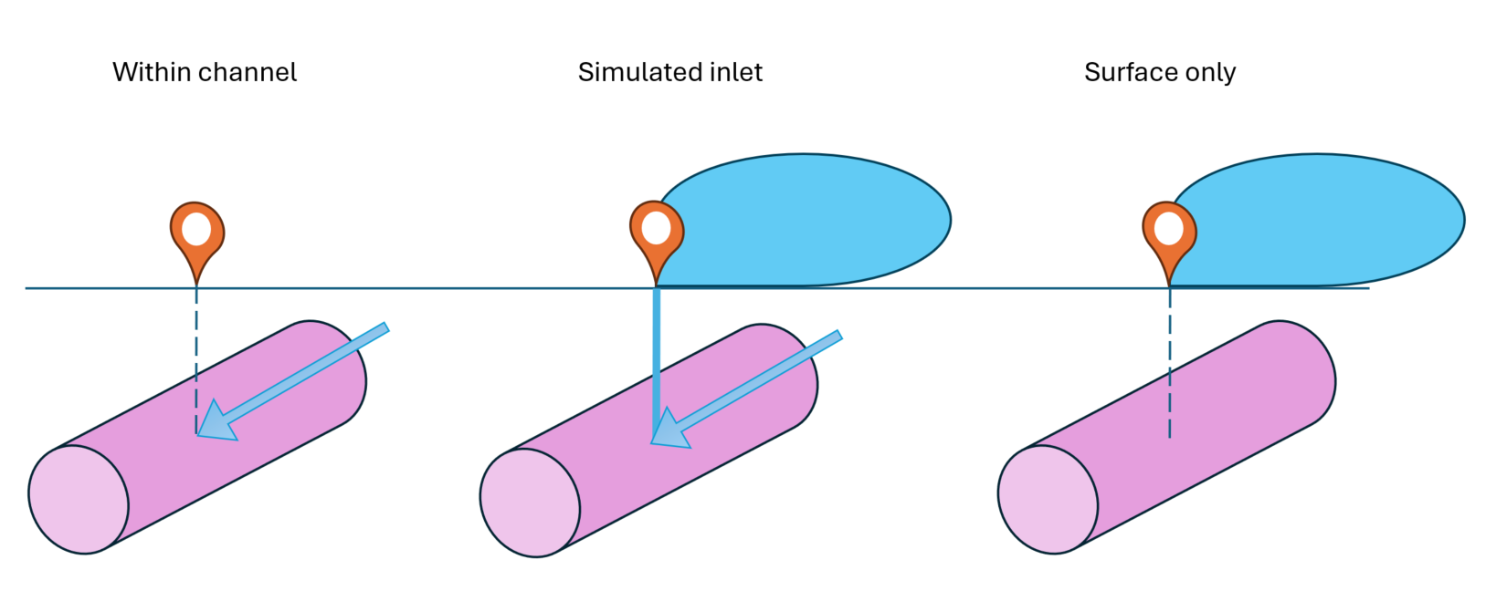
Sewage watersheds
Select how to delineate watershed for sites in sewage lines.
The default value assumes the site is ‘within a channel’, so the watershed is delineated from the upstream sewage network segments (open and closed)
A ‘simulated inlet’ performs a sewage network delineation like the default mode, but additionally simulates an inlet to the sewage pipe at the site’s location and thus combines the sewage flow with a gravitational surface delineation
‘Surface only’ performs a gravitational surface delineation at the site, but does not look at the upstream sewage network.
Upstream watershed delineation
In maps with sewage networks, the watershed of a site can contain the outlets of regular pipes or trunk pipes. Those might transport water from another area of the map to the current watershed. To follow the upstream path of the runoff, it is necessary to follow these pipes to their source and include the network in the watershed. This processing option allows to specify which kind of sewage to follow upstream.
Closed: Only follows underground/closed sewage pipes
Open: Only follows open sewage channels
Both: Follows both types (closed and open)
Beware: in very dense open sewage networks, following open channels might introduce a large amount of recursive delineation operations and take longer to process.
Sewage buffer
To simulate sub-surface sewage contribution from nearby buildings to closed sewage lines, watersheds are derived by buffering the lines with a specified buffer width (because individual inlet points to the sewage network are not known). Change the buffer width (in meter) if you wish to assign more or less population living in the catchment area of a sewage system.
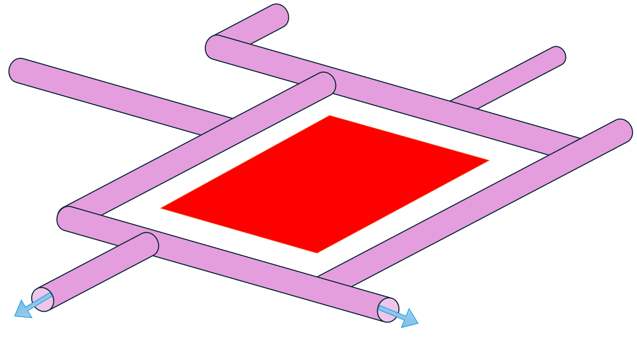
Enclosed areas
Delineating watersheds in sewage networks might leave holes in enclosed areas because the chosen buffer around sewage lines is too small. Enclosed areas (up to a maximum area size) are therefore added to the watershed, assuming that runoff from these areas will end up in the surrounding sewage lines. Specify the maximum enclosed area size (in square kilometer) threshold.
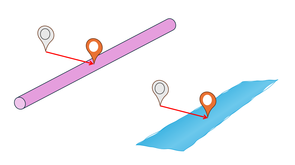
Site snapping
Prevents sites from being slightly displaced. Select the maximum distance (in meter) used for snapping sites to nearby waterways (sewage pipes, rivers and drainage lines).
Sewage line metadata
The metadata for sewage lines has a big impact on the map processing. The main options are: open, closed, trunk.
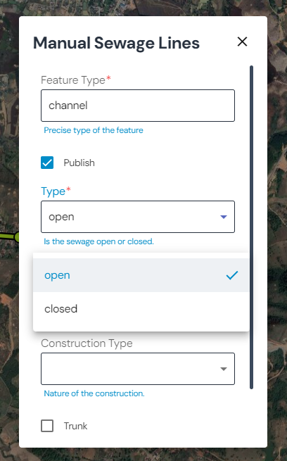
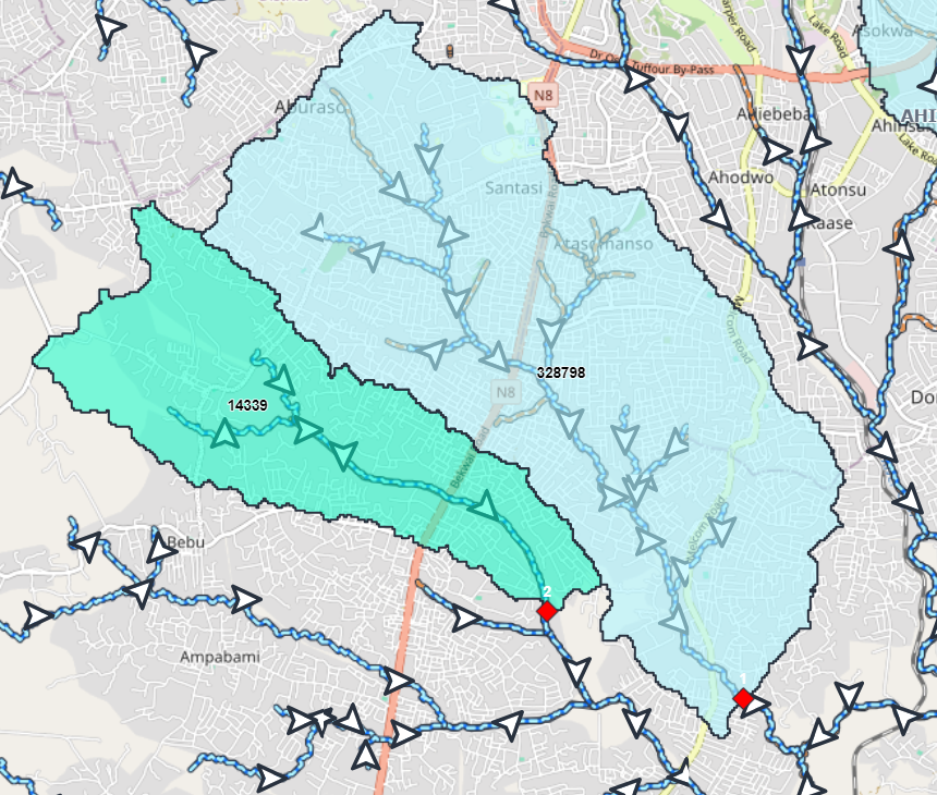
Open sewage lines
The DEM is used to infer the flow direction of open sewage lines. Here is an example of an open sewage delineation, using the DEM to infer the sewage flow:
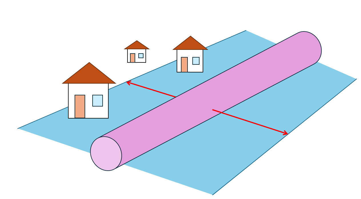
Closed sewage lines
Only the direction of the digitized closed sewage lines is used to infer the flow direction. This can always be used when the direction of a flow is known or when the flow does not follow the slope of a DEM (for instance underground sewage and / or flow from pumping stations). Here is an example of a closed sewage delineation:
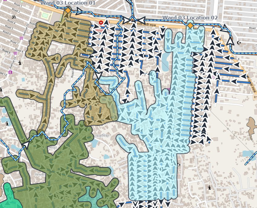
Important
In this case, the sewage lines are buffered with 30m on each side to consider that everyone within this distance on each side of the sewage line is likely to contribute to that line.
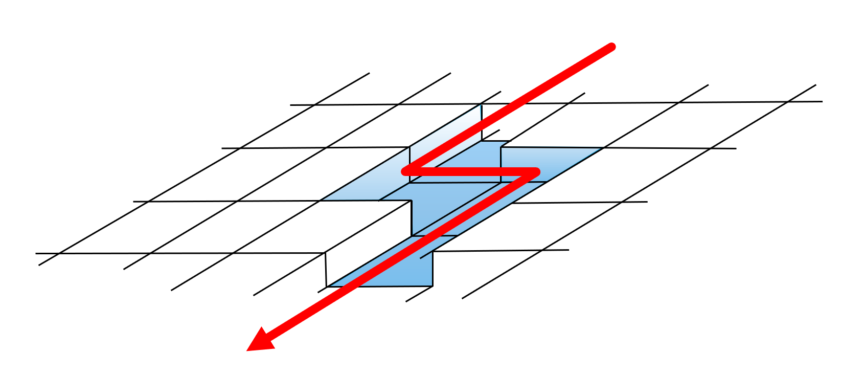
Trunk lines
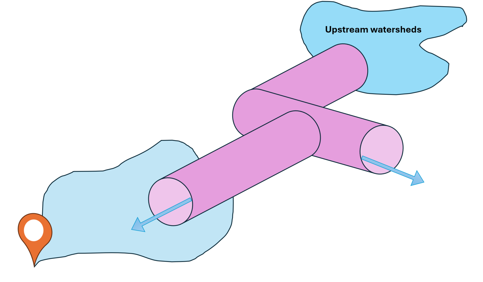
This attribute should be used in cases where pumping stations pump sewage via a trunk line over / under other sewage lines but there are no junctions where the segments cross.
This way, a pipeline can be isolated from the other flows, as shown in this example:
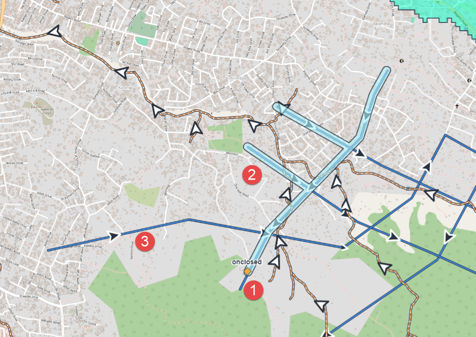
This is a site location with upstream closed sewage pipes
The watershed created takes into consideration all the pipes that intersect upstream
This segment has been labelled as ‘trunk’ segment and thus the intersection is not counted